

E-Motor Encoders
A student brochure for understanding motor feedback selection
E-Motor Encoders
A student brochure for understanding motor feedback selection
|
What is an encoder? An encoder is a feedback device that tells the drive what the motor shaft is doing: position, speed, direction, and motion change. In closed-loop control, this feedback helps the drive command torque and speed accurately, especially in servo, BLDC, PMSM, robotics, CNC, packaging, and automation systems. |
Why are they used? · Position feedback · Speed measurement · Direction detection · Closed-loop motor control |
Two ways to report motor position
|
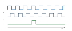
1 Incremental feedback
A/B/Z pulse channels show relative motion and direction. · Outputs pulses as the shaft moves. · Excellent for speed and relative position. · Usually needs homing after power loss. |
2 Absolute feedback
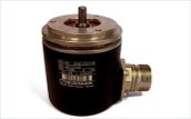
A unique digital value is assigned to each shaft angle. · Knows position immediately after power-up. · Useful when homing is slow, unsafe, or impossible. · Can be singleturn or multiturn. |

Fast learning rule
No single feedback device is best for every motor. The right choice depends on required accuracy, control performance, environmemnt, safety needs, and cost.
|
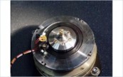
Real optical encoder photo |
Real absolute encoder photo |
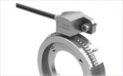
Real magnetic/incremental encoder photo |
|
Page 1 |
Start with the function: speed only, position control, safety, or harsh-duty feedback. |
|
Core Encoder Technologies
Four common options used in industrial e-motor feedback systems
|
1 Optical encoder
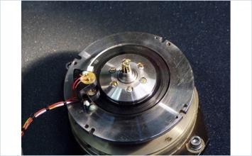
Real optical encoder with code disk. · Precise speed and position feedback. · Coded disk + light sensor. · Best for: CNC, robotics, precision servo axes. · Environment: clean and dry areas. |
2 Magnetic encoder
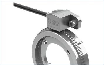
Real magnetic MiniCoder-style incremental encoder. · Robust speed/position feedback. · Magnetic target wheel or ring + sensor. · Best for: dust, oil, and vibration. · Environment: harsh industrial areas. |
|
|
3 Inductive encoder
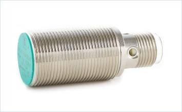
Real inductive sensing reference photo. · Robust absolute/incremental feedback. · Inductive/electromagnetic scanning. · Best for: servo drives, robotics, automation. · Environment: shock and contamination. |
4 Capacitive encoder
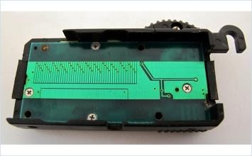
Real capacitive encoder principle photo. · Compact position and speed feedback. · Measures capacitance changes. · Best for: compact moderate-precision systems. · Environment: moderate dirt/grease if sealed. |
|
|
Page 2 |
Optical = precision; magnetic/inductive = robustness; capacitive = compact principle-based feedback. |
|
Rugged Feedback s Interfaces
Resolvers and Hall sensors are often compared with encoders in motor-control design.
|
5 Resolver
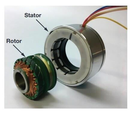
Real resolver / rotary transformer photo. · Purpose: rotor angle and speed feedback. · Specificity: electromagnetic analog feedback device. · Best for: traction drives, aerospace, heavy-duty motors. · Environment: high temperature, shock, vibration. |
6 Hall-effect sensors
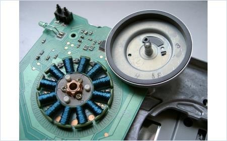
Real BLDC motor board with Hall sensors. · Purpose: simple rotor sector feedback for BLDC commutation. · Specificity: normally coarse, low-resolution position. · Best for: fans, pumps, simple BLDC drives. · Environment: general use where precision is not critical. |
Common motor-feedback interfaces
|
Interface |
What it carries |
Why students should know it |
|
A/B/Z |
Incremental pulse channels |
Simple, common, low cost |
|
Sin/Cos |
Analog sine/cosine signals |
Smooth interpolation and fine control |
|
SSI |
Serial absolute position |
Straightforward point-to-point absolute feedback |
|
BiSS-C |
Fast open digital interface |
High-speed absolute feedback |
|
EnDat |
Digital position + parameters + diagnostics |
High-end servo feedback and diagnostics |
|
HIPERFACE DSL |
Digital motor feedback over one cable |
Reduces cabling in servo systems |
|
Student tip: When reading a motor datasheet, check both the feedback technology and the interface. A high-resolution encoder is only useful if the drive can read its signals correctly. |
||
|
Page 3 The encoder is not only a sensor; it is part of the drive-control system. |
||
Selection Guide
Choose feedback by control need, environment, and system cost.
|
Application / condition |
Recommended feedback |
Why |
|
|
Clean precision servo axis |
Optical or Sin/Cos encoder |
Highest precision |
|
|
Dusty or oily factory motor |
Magnetic or inductive encoder |
Contamination resistance |
|
|
High-vibration automation |
Inductive encoder or resolver |
Rugged sensing |
|
|
High-temperature motor |
Resolver |
Extreme thermal robustness |
|
|
Low-cost BLDC motor |
Hall sensors or magnetic encoder |
Simple commutation |
|
|
Safety-rated servo drive |
Absolute encoder with safety support |
Position + diagnostics |
|
|
Quick takeaways · Optical encoders offer the highest precision. · Magnetic encoders are strong in dirty environments. · Inductive encoders combine robustness and modern servo performance. · Resolvers are best for extreme conditions. · Hall sensors are best for simple low-cost commutation. |
Common student mistake Do not select a feedback device by resolution alone. Also check operating temperature, vibration, IP protection, cable length, electrical noise, drive compatibility, and whether the system needs absolute position after power-up. |
||
Image credits and notes
|
Image |
Credit / note |
|
Optical encoder |
Wikimedia Commons, “Optical encoder.jpg”, Charly Whisky, Free Art License. |
|
Magnetic encoder |
Wikimedia Commons, “MiniCoder.jpg”, Lenord, Bauer C Co. GmbH, CC BY-SA 3.0. |
|
Absolute encoder |
Wikimedia Commons, “Rotatory EnDat Encoder.jpg”, Smial, GFDL / CC BY-SA 3.0. |
|
Inductive reference |
Wikimedia Commons, Pepperl+Fuchs inductive proximity switch, Axel Hindemith, CC BY-SA 3.0. Used as an inductive sensing reference, not a rotary encoder product photo. |
|
Capacitive reference |
Wikimedia Commons, “Digital caliper capacitive linear encoder…”, Dims110, CC BY-SA 4.0. Used to show capacitive sensing principle. |
|
Resolver |
https://ez.analog.com/ez-blogs/b/engineerzone-spotlight/posts/resolving-an-encoder-from-a-resolver |
|
Hall sensors |
Wikimedia Commons, “Floppy drive spindle motor open.jpg”, Priwo, CC BY 3.0. The board includes Hall sensors. |
|
Page 4 |
|


